Build Guide
Download All Files
Grab everything you need from the GitHub repository: Gerber files for PCB fabrication, the full bill of materials, enclosure STL/STEP files, and pre-compiled firmware hex files.
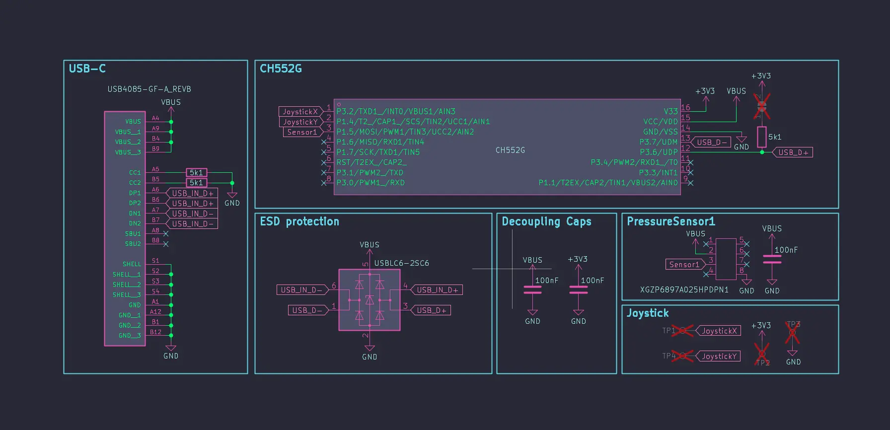
Source the Components
Order all parts from the BOM. LCSC stocks the CH552G, pressure sensor, and passives at the lowest prices. The joystick module is widely available on AliExpress. Mouser and DigiKey work too.
Fabricate the PCB
Upload the Gerber files to a PCB manufacturer such as PCBWay or JLCPCB. Order the bare PCB — no assembly. Standard 2-layer, 1.6 mm FR4, HASL or ENIG finish.
Solder the Components
Assemble all SMD components onto the bare PCB. Work inside-to-outside — smallest and most central parts first, leaving the pressure sensor for last. The CH552G (SOP-16) and 16-pin USB-C connector are the most demanding pads — take your time and check continuity before powering on.
Build the Enclosure
3D print the enclosure using the STL files. Resin gives the best surface finish; FDM works too with careful layer settings. Alternatively order the enclosure from a CNC or resin printing service.
Wire and Assemble
Solder wires to the joystick first — bridge the two GND legs together and the two VCC legs together at the joystick so only one GND and one VCC wire run to the PCB. Push the silicone tube through the sensor hole from outside, leaving extra length inside. Lead the PCB into the case USB-C end first, connect the tube to the sensor port, then pull the tube taut from outside while pressing the PCB until you hear a snap and it sits flush. Fit the joystick in its pocket and secure with super glue. Apply glue to the lid contact points, align the lid, and hold until set.
Flash Firmware
Use the flash tool below. A fresh board from the manufacturer enters bootloader automatically on its first plug-in — just click 'Connect CH552 Bootloader'. For subsequent flashes, click 'Reset to Bootloader' first to send the serial reset command. Emergency fallback only: unplug, short the two boot pads on the PCB with tweezers while plugging in, then release. Select your variant (Single / Dual / Plus) and flash.
Go to Flash Tool ↓Configure
Plug in the finished device and use the configurator below to assign macros, adjust sensitivity, and calibrate joystick zones.
Go to Configurator ↓